
Tables can't be imported directly. Please insert an image of your table which can be found here.
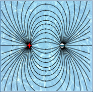
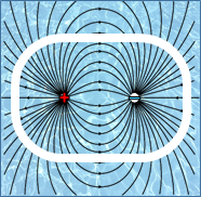
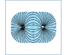
Figure 1: Current lines that measure the EC when the probe is placed in solution.
Figure 2: The shroud is placed on the probe and has some of the current field lines inside that area and some outside. Then looking at figure 3 we can see the effects of this.
Figure 3: The effect of the shroud on the measured current field lines. All current flow is confined to within the shroud as the electrical current cannot travel through the plastic.
When the EC probe is placed in a solution a voltage is applied to it. This voltage generates a current that is conducted between the two oppositely charged electrodes. While most of the current will take the path of least resistance (shortest distance), there will be a percentage of the current which will take a longer route. The theoretical field lines in figure 1 show the many different paths that the electrical current could take and how this occupies a large, almost infinite area. This wouldn’t cause a in measuring the EC of solution if the solution volume was very large, however if an obstructing object such as the side or bottom of a container was within this field, the EC reading would change and so compromise the ease of constantly taking a reliable and accurate EC measurement.
The Shroud contains the electrical field within a set volume around the two electrodes (figure 2 and 3). This area will remain constant and prevent any discrepancies in the EC measurements from occurring, thus resulting in a much more reliable measurement.